Packaging-line integration
Build the mechanical, product-flow and controls interface schedule.

Fully automatic liquid bottling line integrating bottle unscrambling, servo filling (4 heads), capping, and single‑ or double‑side labeling for flat/square bottles. Modules are selected to your product, container and speed, and integrated on a synchronized conveyor with central controls.
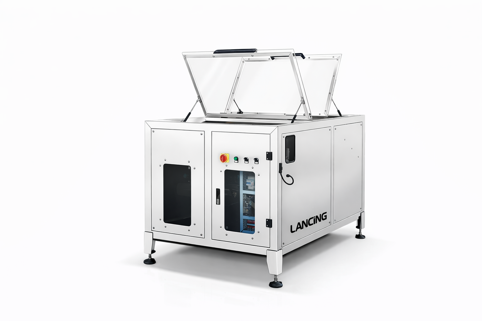
4 filling heads with recipe control for fast changeovers and consistent dosing.
Single or double side labeling for square/flat bottles.
Central controls synchronize unscrambler, filler, capper and labeler.
Line speed and modules tailored to your product and container.
Cosmetic, beverage, pharmaceutical and more.
Built to order per your product, speed and budget.
Shampoo, lotion, creams.
Juice, tea, RTDs.
Detergents, cleaners.
Tell us about your products and line requirements. We’ll confirm compatibility and quote the best configuration.
Application and selection guidance
The line shown combines bottle unscrambling, four-head servo filling, capping, labelling and synchronised conveyors. Each module must be proven with the same product and pack so that the complete output is realistic.
The unscrambler and conveyor must orient and transfer every bottle format without scuffing, tipping or creating unstable gaps. Lightweight and asymmetric bottles can require format-specific handling.
The servo filler, product path, nozzle and capping method are selected from the liquid or paste and the closure. A line cannot be finalised from bottle dimensions alone.
Single- or double-side labelling is shown for flat or square containers. Label stock, panel geometry and product control must be checked before the discharge and downstream handling are fixed.
The slowest proven operation sets the line output. Cap feeding, label reel changes, product replenishment and minor stops should be included when setting a sustainable target. Accumulation can isolate short interruptions but cannot compensate for a permanently undersized station.
Central recipe control can coordinate established formats, while physical changeovers still include guides, nozzles, cap tooling, label position and sensors. List the full format matrix and normal run lengths so the changeover strategy is clear.
Provide a dimensioned floor plan, product-flow direction, utilities and access routes. Existing machines need conveyor height, speed and interface details. The project specification should identify the product, container, closure and label used to assess dose, torque, placement and output.
Related modules can be reviewed in filling, capping and labelling machinery.
Specify the whole pack route and acceptance conditions before fixing individual module capacities.
Discuss an automatic bottling lineThe page shows a four-head servo filler as the current configuration example. Final head count and pump arrangement should be selected from the product, dose and required line output.
The page describes liquid or paste configuration, but the product path, pump, nozzle, cleaning and rate must be selected for the actual products.
Output should be agreed against a defined product and pack, with the line setup, replenishment and acceptance method stated. Individual reference speeds are not enough.
It may be possible when dimensions, conveyor interface, trigger signals, fault outputs and practical capacity are supplied and compatible with the new line.
Typical changes include guides, filler recipes and nozzle position, cap tooling or feeder settings, label setup and sensors. The exact sequence depends on the formats.
Complete bottling-line resources
A filling, capping and labelling line must be engineered as a connected system. The sustainable result depends on container supply, component feeding, transfer, inspection, recovery and changeover as well as each machine cycle.
Prepare a format matrix covering product, fill, container, closure, label and coding requirements. Mark the least stable bottle, smallest opening, longest closure component and most difficult label. The line layout should show direction, datum heights, access, operator replenishment, reject collection and space for cleaning and change parts.
Agree ready, running, blocked, starved, fault and emergency-stop boundaries for each station. Define accumulation behaviour and restart after a local stop. The acceptance protocol should test normal production, format change, replenishment, deliberate faults, restart, rejected packs and the handover between factory and site-dependent checks.
Build the mechanical, product-flow and controls interface schedule.
Confirm access, footprint, services, environment and installation responsibilities.
Create measurable factory and site acceptance evidence.
Ready to discuss the application?
Send the application details to Lancing for a tailored machinery review.
Automatic line questions
A filling, capping and labelling line should be specified as a connected process. These questions focus on bottlenecks, third-party interfaces, fault recovery and acceptance—areas that can be missed when each module is considered separately.
Identify the stage with the lowest sustainable acceptable output under the real product, pack and changeover conditions. Include feeding, inspection, manual replenishment, accumulation and downstream packing rather than comparing isolated headline cycle rates.
Build a simple process map with expected cycle, batch interruptions and recovery time for each stage. The objective is not to make every machine identical in speed, but to provide enough capacity and buffering for the line to meet the agreed finished-pack duty.
The output-rate guide explains the calculation framework.
Define physical transfer, direction, height, pack condition, speed or demand signals, permissives, emergency-stop boundaries, fault status, reset responsibility and any data exchange. Name the party responsible for each side of the interface.
A drawing alone is not enough when controls must coordinate. Use an interface schedule that can be reviewed before manufacture and repeated during FAT or SAT with simulators or the actual connected machine where available.
See the line-integration guide.
Define what constitutes a rejected pack, where it is detected, how it is tracked and where it is removed. Then define the line response when the reject bin is full, the reject confirmation fails or a machine stops with packs between stations.
Recovery should prevent double filling, uncapped release, incorrect labels or loss of pack identity. A written sequence is more useful than a general statement that the line will stop on fault.
The coding and inspection guide covers verification and rejection.
Include the normal production format, the most difficult format and every changeover that introduces different tooling, recipes or transfer conditions. Acceptance should not be based only on the easiest middle-sized bottle or a single product condition.
Agree what will be demonstrated at factory acceptance, what must wait for site utilities or production product, and how any third-party machine will be represented. Record exclusions so they are not mistaken for accepted capability.
Use the FAT and SAT guide and URS guide together.
Provide a process sequence, line layout, format matrix, third-party interface list and acceptance priorities so the complete line can be reviewed as one controlled system.
Discuss the applicationAutomatic bottling line project definition
The existing product page describes the bottling-line proposition. Project definition should also identify the difficult bottle, product condition, closure feeding, label construction, accepted fill result, code and inspection data, reject response and line recovery sequence.
Define dimensions, tolerances, stability and orientation.
Define feeding, neck finish, orientation and acceptance.
Define states, recipes, coding, inspection and recovery.
Use the packaged-goods quantity-control guide when the line makes up regulated prepackages in Great Britain, and agree the packer's measurement and record system separately from the filler setting.
Line-balance evidence
Use the intended product and pack range over an agreed representative run. Count accepted finished packs and record refills, rejects, machine states, blockages, starvation, manual tasks and recovery after normal stops. A short peak rate does not represent sustained production.
Use state evidence before changing speeds or buffers.
Specify sustained good output and conditions.
Agree samples, run duration, changeovers and issue handling.
© Copyright 2025 by Lancing Ltd - all right reserved terms & conditions